
How to Test the Fit of Two 3D Printed Parts
Before printing a full enclosure or bracket, print a small copy of the joint. These two models let you try four clearances with the same tab and see which fit you can assemble by hand.
Start with four clearances
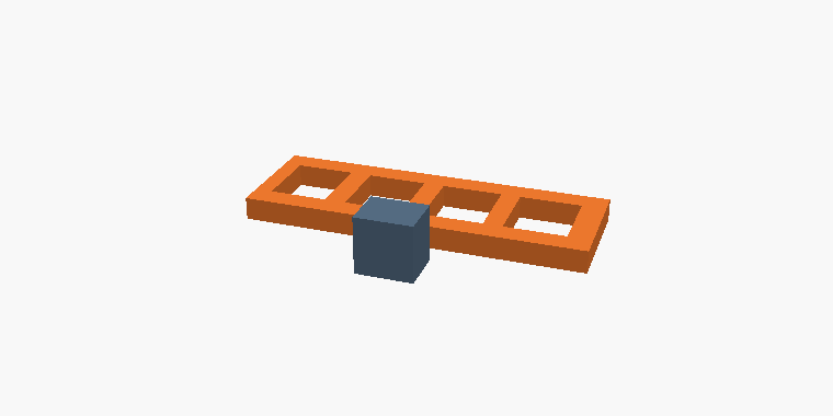
Clearance is the gap you design between mating surfaces. Tolerance describes how far the finished dimensions can vary from the design. Subtract the tab width from the slot width to get total clearance. For a centered tab, half of that gap is on each side.
The tab is 10.00 mm wide in the model. The slots run from narrowest to widest across the gauge.
| Slot width | Total gap | Gap per side |
|---|---|---|
| 10.20 mm | 0.20 mm | 0.10 mm |
| 10.40 mm | 0.40 mm | 0.20 mm |
| 10.60 mm | 0.60 mm | 0.30 mm |
| 10.80 mm | 0.80 mm | 0.40 mm |
These are design dimensions. Material, print settings and orientation can change the finished fit.
Print, measure, and try each slot
- Import both files in millimeters at 100% scale. Use the same material and print settings you plan to use for your part.
- Let the parts cool. Measure the tab across its mating faces and use the inside jaws of a caliper to measure each slot. Measure above the first layer as well if the edge is flared.
- Try the tab in each slot without forcing it. Record which slots bind, slide with light resistance, or feel loose. Write down the material and orientation so you can repeat the result.
For example, if your caliper reads 10.36 mm at the slot and 10.08 mm at the tab, your measured clearance is 0.28 mm in total. Repeat the check on a small section of your actual joint before committing to the full part, especially if it prints in a different direction.
Prusa’s reference on designing mating partsOrder a fit-check prototype
Bring both mating files and note which faces need to slide or hold. Include the dimensions that matter and any measurements from an existing part.